

The PLC
About the Simutech PLC
The Simutech PLC consists of a combination of hardware components and software programming.
The hardware connects directly to external sensors, receiving analog process information in real time. It also connects to external devices such as heaters, fans, foggers and lights.
The software uses the information it receives from the external sensors to actuate output devices as needed to maintain optimum conditions in the greenhouse.
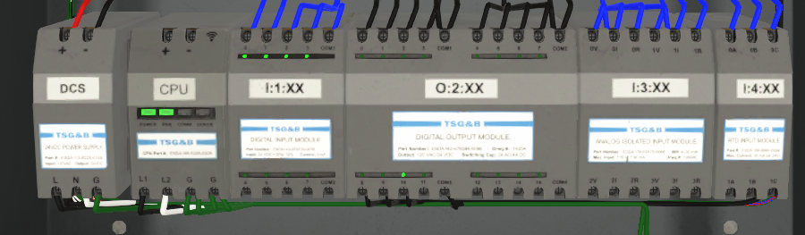
PLC Hardware Components
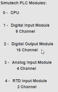
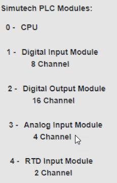
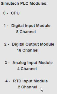
The PLC Components can be found in the Control Panel and include:
- A power supply
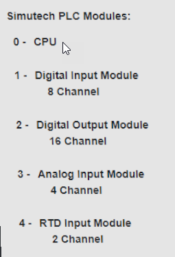
- CPU
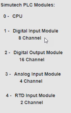
- Digital Input Module – 8 Channel
- Digital Output Module – 16 Channel
- Analog Input Module – 4 Channel
- RTD Input Module – 2 Channel
PLC
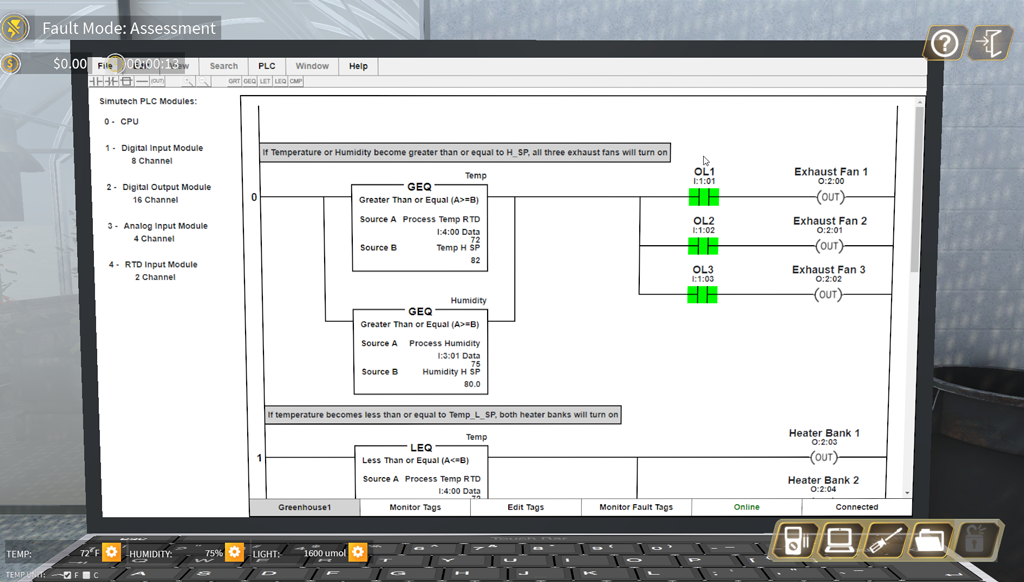
PLC Software – The Laptop Interface
To access the PLC software, click on the laptop icon located on the toolbar on the bottom right of the screen. The laptop will appear, with the loaded program defaulted in Run mode.

Toolbar Laptop
Toolbar Laptop
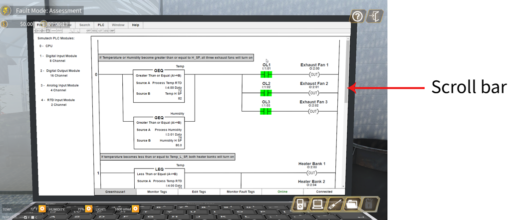
Viewing the Program
The scroll bar can be used to view the entire program.
Toolbar Laptop
Opening Laptop Screen
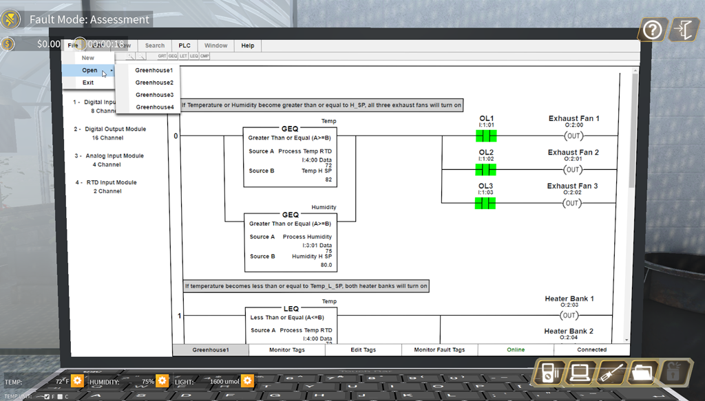
Loading Offline Programs
Depending on the troubleshooting scenario, it may be necessary to load a different program. To view other programs that are available, select the File tab, Open… and choose the program you would like to view. The chosen program will be automatically loaded into the PLC and set to RUN mode.
Loading Offline Programs
Module – CPU
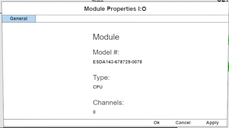
The user can view the Module Configuration for any module attached to the PLC.
The CPU Module only has a General Tab, listing the serial number and type of CPU. All modules will include a General Tab.
CPU 1
CPU 2
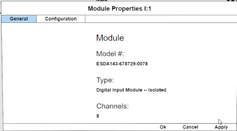
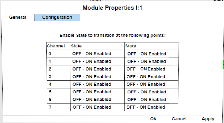
Module – Digital Input Module
The Digital Input Module also has a General Tab, but an added Configuration tab sets the transition points for all of the inputs. As shown, all inputs are set to trigger at the OFF to ON transition point. The trigger state is preset and not changeable by the user.
Dig Input Module 1
Dig Input Module 2
Dig Input Module 3
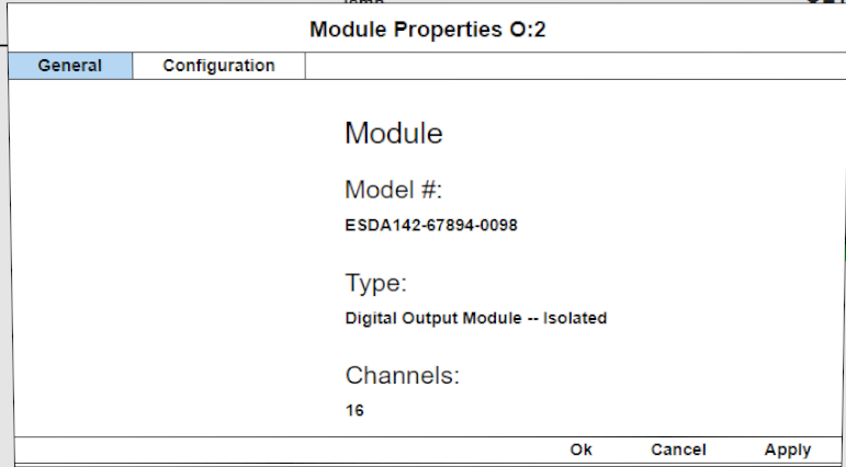
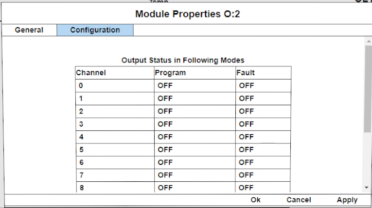
Module – Digital Output Module
The Configuration tab for the Digital Output Module specified when outputs will be turned off. In this case, in Program Mode or if a Fault is detected, the outputs will automatically be turned off. These values are preset and not changeable by the user.
Dig Output Module 1
Dig Output Module 2
Dig Output Module 3
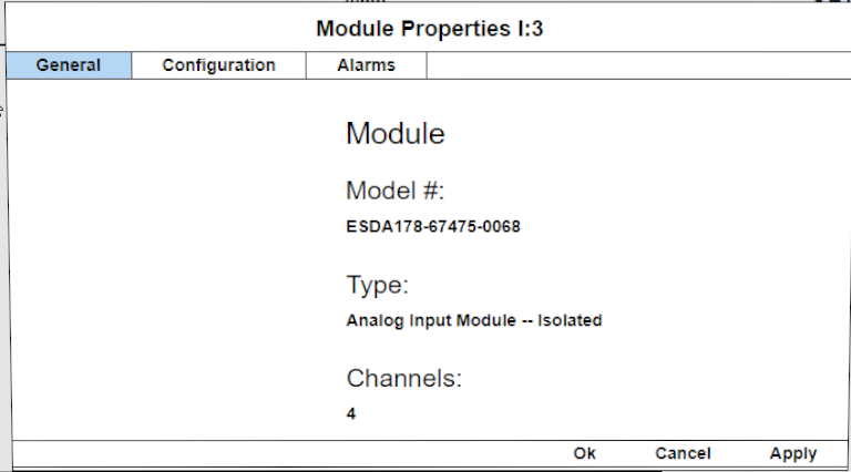
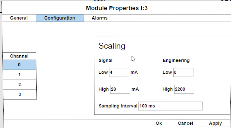
Module – Analog Input Module
In addition to the General Tab, the Analog Input Module includes a Configuration Tab and an Alarm Tab. The Configuration tab sets the Scaling for the channel and the Alarms Tab sets the points for the internal alarms.
Analog Module 1
Analog Module 2
Analog Module 3
Analog Module 4
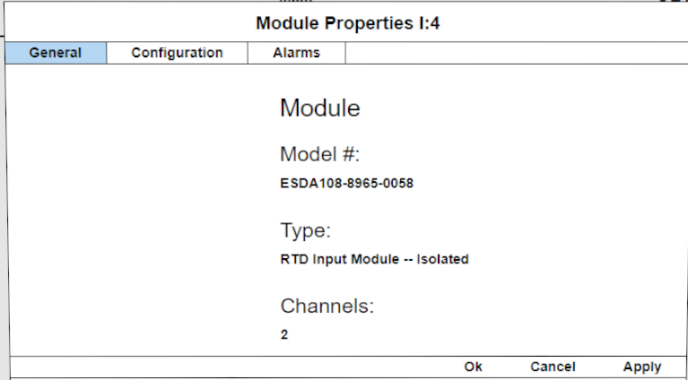
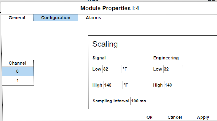
Module – RTD Input Module
In addition to the General Tab, the RTD Input Module also includes a Configuration Tab and an Alarm Tab. The Configuration tab sets the scaling for the channel and the Alarms Tab sets the points for the internal alarms.
RTD Module 1
RTD Module 2
RTD Module 3
RTD Module 4
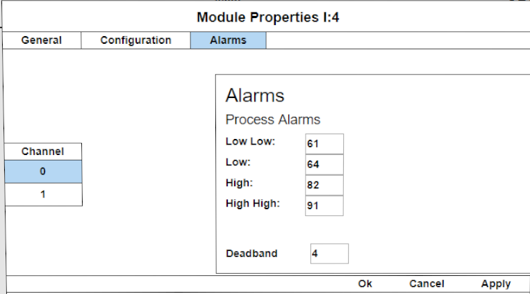
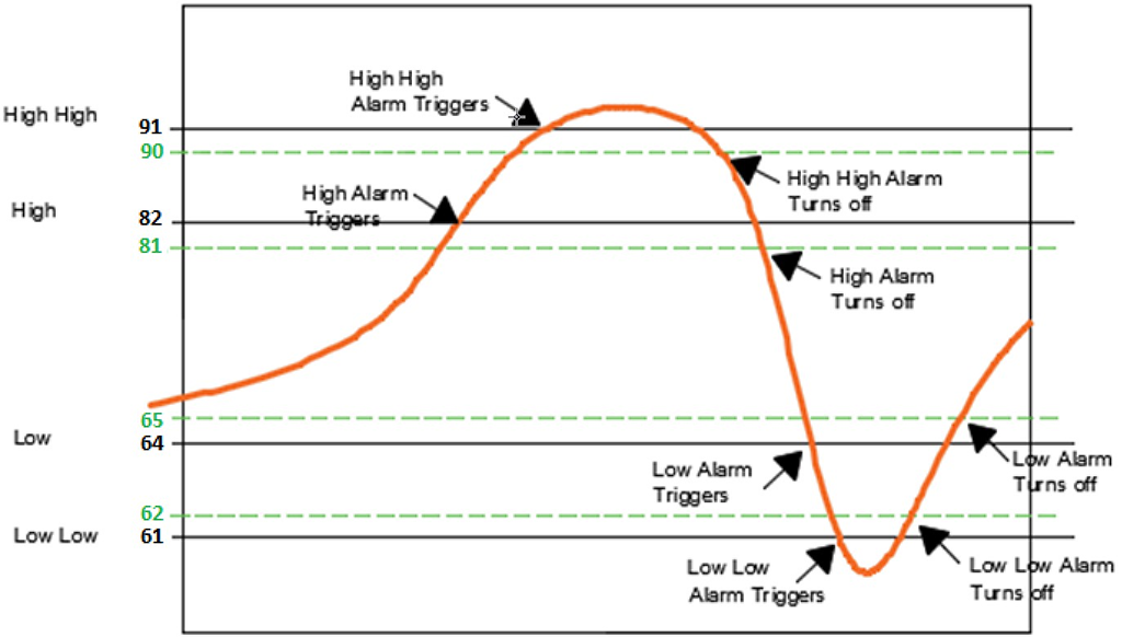
Alarms and Deadband
The Alarms tab sets values for 4 levels of alarms that are tied to internal addresses in the PLC. The graph below illustrates how the deadband ties into the Alarm actuation points if the deadband were set to 1. Deadbands generally prevent cycling in a process where changes in a Process Value are slow to respond such as changes in temperature and humidity. In this case it will prevent the cycling of an internal flag.
RTD Module DB1
DB1
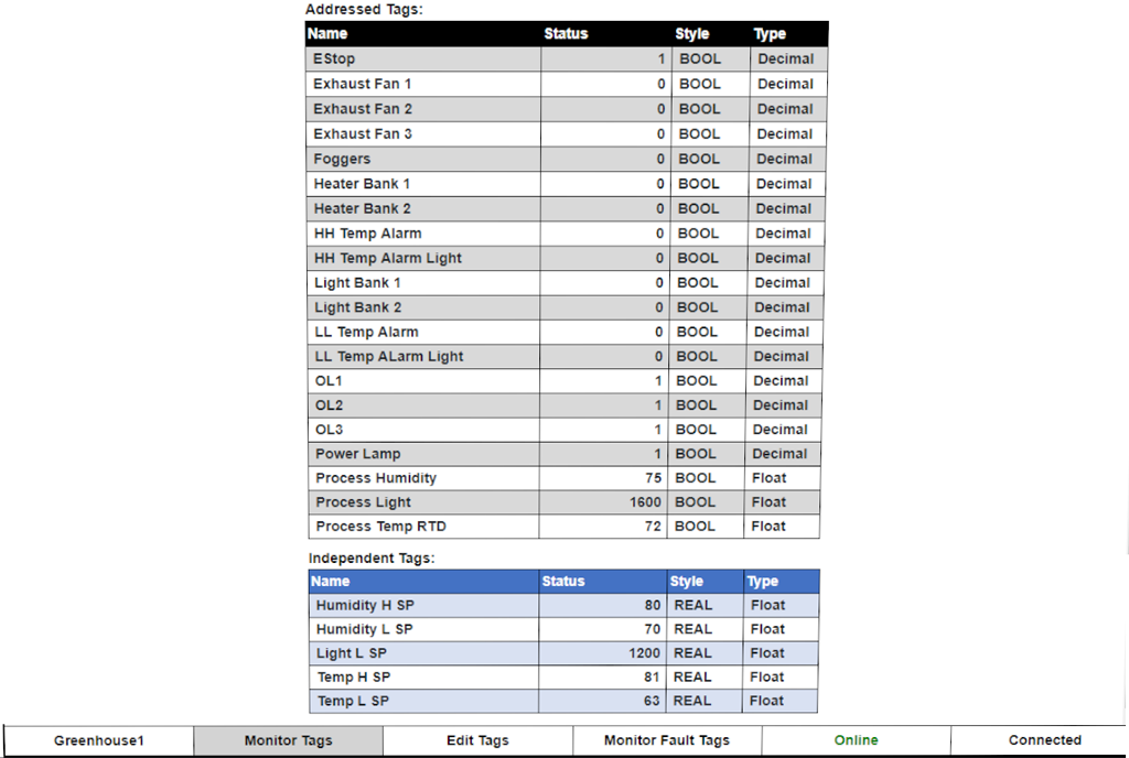
Monitoring Tag Tab
The Monitoring Tag Tab allows the user to see the digital and real time process values for all inputs and outputs whether digital or analog. This tab is also where the user would create values for independent tags, that is tags that are not associated with an address.
Monitor Tags Tab
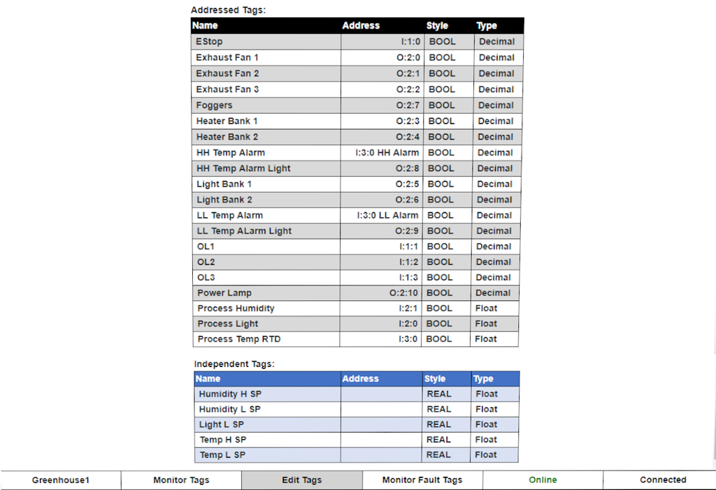
Editing Tag Tabs
The Editing Tag Tab allows the user to see the list of addresses for all inputs and outputs whether digital or analog.
Notice that Independent Tags do not have physical addresses.
Edit Tags Tab
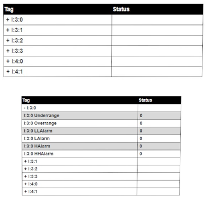
Monitoring Fault Tag Tab
The monitoring Fault Tag Tab allows the user to see the digital status (1 or 0) of the following faults:
- Underrange
- Overrange
- LL Alarm
- L Alarm
- H Alarm
- HH Alarm
To select which channel to view, click on the + symbol beside the desired channel.
Monitor Fault Tag Tab