

The Multimeter
About The Multimeter
The Multimeter is a vital tool for diagnosing problems with the process.
The multimeter allows you to:
- Take voltage readings (AC and DC)
- Take resistance readings
- Take current readings (AC clamp and DC probe)
Multimeter
Accessing the Meter
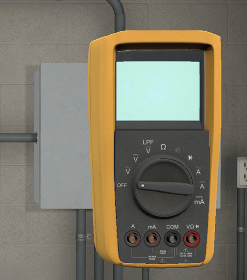
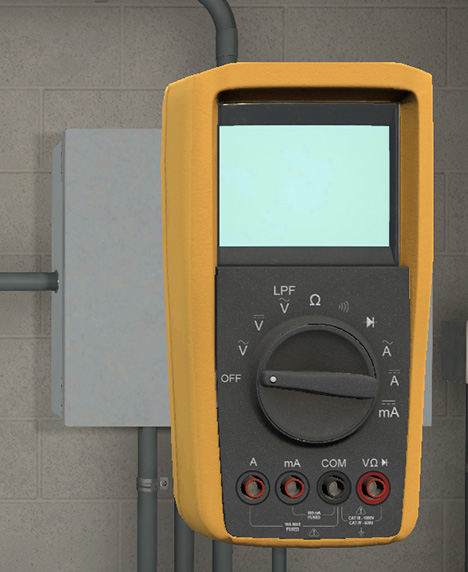
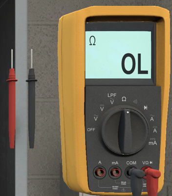
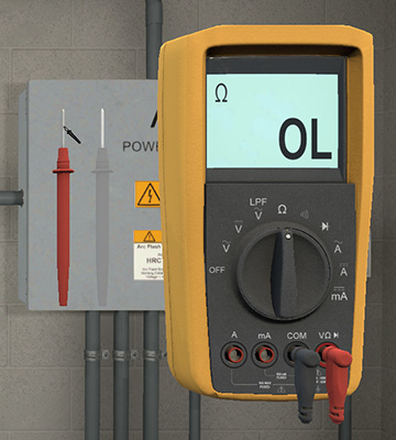
The Multimeter can be accessed by clicking on the meter icon located on the toolbar at the bottom left side of the screen. The meter will remain onscreen until the icon is clicked again. When the meter appears, it is defaulted in the OFF position and the leads are not displayed. The leads will be displayed after the measuring unit has been selected.

Toolbar Multimeter
Multimeter
Multimeter On
Attaching the Meter
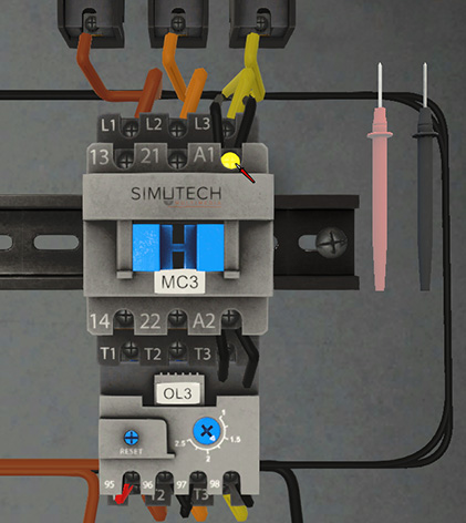
Once the meter has appeared, select a lead by clicking on it. The lead colour will become pale, indicating that it has been selected. The cursor will now appear as the lead you have selected. To place a lead, hover over the screw or wire you wish to connect to until it glows yellow and then click. The selected meter lead will automatically attach
Screwdriver Reconnect 1
Screwdriver Reconnect 2
Screwdriver Reconnect 3
Taking Voltage Measurements
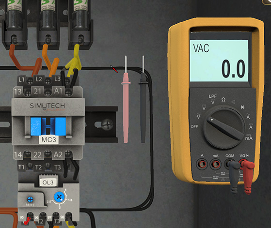
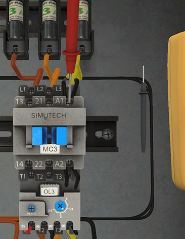
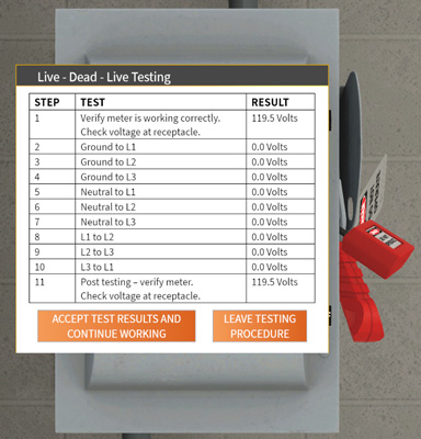
Voltage measurements are taken on live circuits. There is no need to Lockout the system or LDL. Open up the meter and set to Volts (AC or DC). Place the leads across the measurement point.
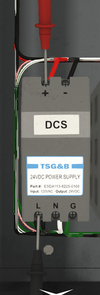
Voltage Measurement set for DC

Voltage DC
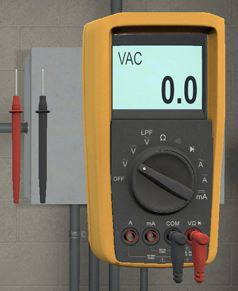
Voltage Measurement set for AC
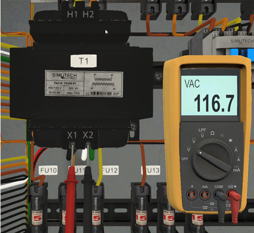
Voltage AC
Voltmeter tips
Tips for taking voltage measurements:
- The voltmeter is often the best tool for finding opens in a circuit
- Voltmeter readings are taken in parallel on a live circuit
- Don’t take readings between the power and control circuits or between AC and DC circuits. To do so will result in the Meter Tip message (as seen on the right)
- Use ground as a reference point when taking readings in AC control circuits
- In DC control circuits it is best to use either the power supply pos(+) or neg(-) as a reference point
Voltage DC-AC
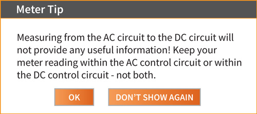
Voltage DC-AC Warning
Taking Resistance Measurements
Lockout the circuit and verify with LDL. Set the multimeter to read resistance. Disconnect at least one wire. Resistance measurements must be taken on a locked-out circuit.
LDL Confirm
Meter Resistance
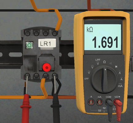
Meter LR1 Coil
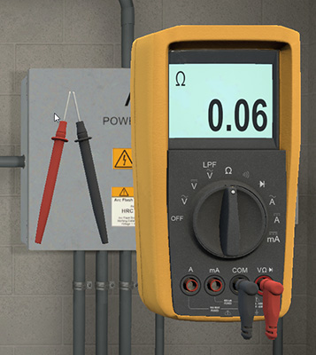
Testing the Meter Leads
You can test the meter leads by touching them together and measuring the resistance. It should be very low. To do this, select one of the meter leads and then once the cursor has changed to that meter lead, click on the other lead. The meter tips will come together, and the resistance value will display.
Test Leads 1
Test Leads 2
Ohmmeter tips
Tips for taking resistance readings:
- Ohmmeters are generally the tool of choice for finding shorts
- Resistance readings are taken in parallel on a dead circuit
- Make sure you have locked out the circuit and performed an LDL
- Open a point in the circuit to ensure the integrity of your measurement
- Although it is a good practice to disconnect only one wire end at a time, there are instances where both ends of a single wire should be disconnected
- If you do remove more than one wire you will receive the following message

Resistance Meter Tip
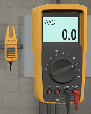
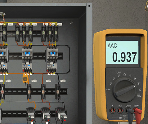
Taking AC Current Measurements
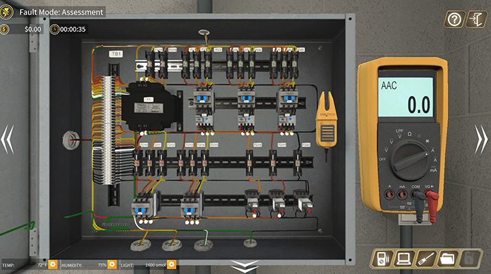
AC current measurements are taken on AC portions of the circuit using a clamp. The clamp is placed around a wire to measure the current flowing through it. To take an AC measurement, set the multimeter for AC current. When you choose AC current, the points available for current measurement will appear as white balls. Clicking on one of these points will attach the AC clamp meter and the current reading will display on the ammeter.
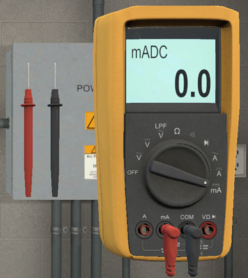
Taking DC Current Loop Measurements
To measure the DC loop current, power must first be locked out and LDL verified. Insert the meter in series in the loop and turn the power back on.
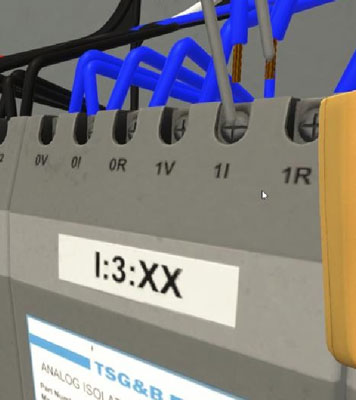
DC loop current measurements may be taken anywhere in the current loop
- At the input module
- At the terminal block
- At the transducer
Meter DC Loop Current
DC Loop Current
Ammeter tips
Tips for taking current readings:
- The ammeter is used to measure the amount of current flowing in various parts of a circuit
- AC current measurements are taken using a clamp meter where power does not have to be disconnected
- AC current measurements make the most sense when testing and comparing 3 phase loads
- DC current measurements are used to measure current in a transmitter or transducer current loop
- DC measurements are taken with probes where the power must be disconnected, the probes connected in series and then power returned to the circuit