

RTD
RTD Sensor
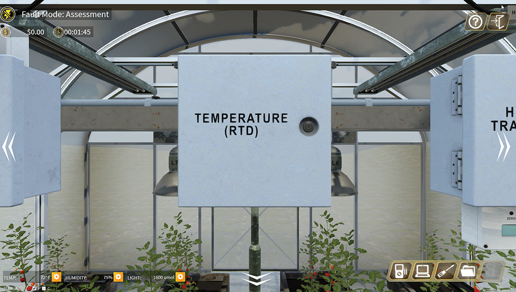
The RTD sensor is located on the center of the overhead beam that passes through the center of the greenhouse.
To zoom in on the RTD sensor, click on it.
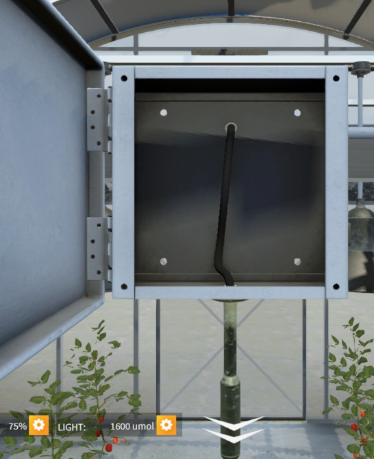
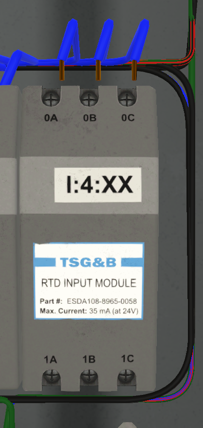
The RTD sensor is a sealed unit, which includes a 50ft cable. No measurements may be taken inside the RTD terminal box. Measurements may be taken at the terminal block or at the RTD Input Module itself. Refer to the documentation for location and specific values.

Greenhouse
RTD zoom
RTD box
The Pt100 .00385 Sensor
The Pt100 .00385 measures resistance as it responds to changes in temperature. The reference table shown below can be used to calculate and confirm circuit values. The reference table is available in the User’s Manual
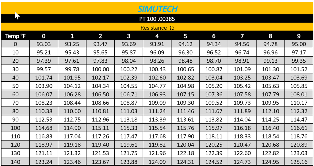
RTD Reference Table
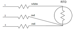
RTD 3 wire
Changes in resistance are very small in relation to the changes in temperature. Because of this, line resistance becomes significant in an RTD’s transmission line.
A three-wire RTD consists of three wires, all the same length. Two of the wires are connected across the RTD, the third sits in parallel to the second wire. The RTD resistance is measured across pins 1 and 2. The resistance between 2 and 3 reflect the actual wire resistance through wires 1 and 2. This resistance is then subtracted from RTD resistance measurement. The remaining resistance is then referenced to the RTD table.
RTD Resistance Measurements
RTD Measure ments may be taken at the terminal block or at the RTD Input Module. 0A to 0B measures the RTD, 0B to 0C measures the lead line resistance.
Example:
You are measuring 113.62Ω between wires 1 and 2
You are measuring 1.53Ω between wires 2 and 3
RTD resistance = 113.62 – 1.53 = 112.09
RTD Module disc
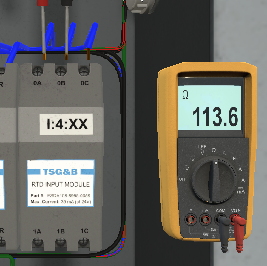
RTD 113.62
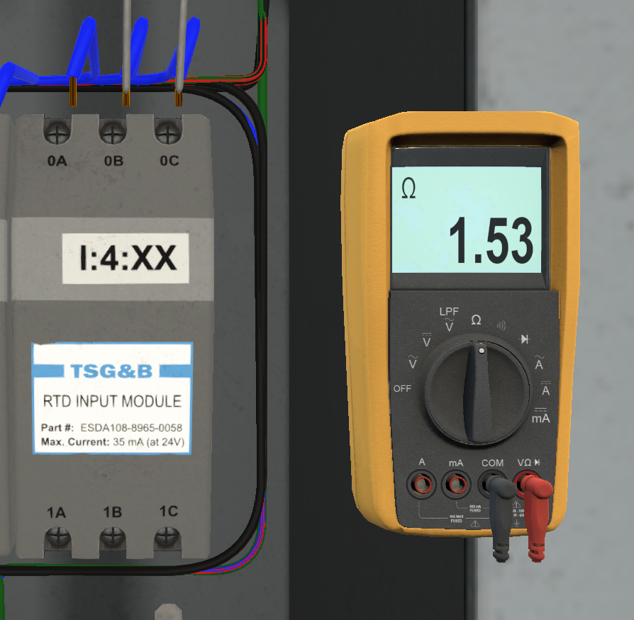
RTD 1.53
From the table you can see that the temperature is approximately 88°F.
Compare this to the Greenhouse Conditions to verify.
If the Greenhouse Conditions do not match your calculations then it is time to look more closely at the RTD.

Temp 88
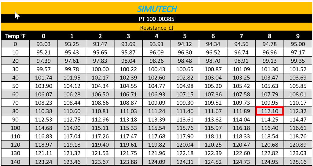
RTD Reference Table
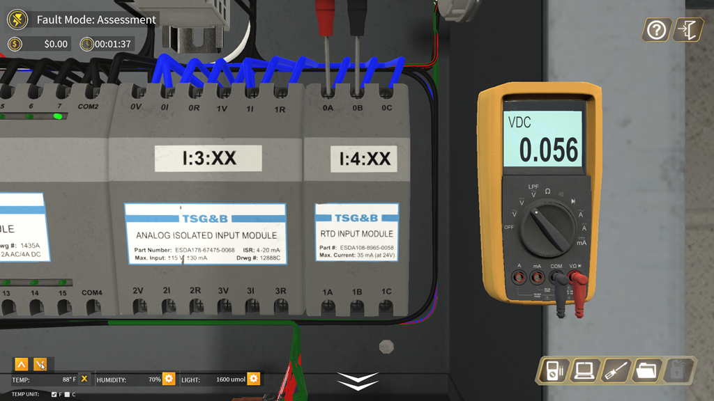
RTD Input Module Voltage Measurements
An internal excitation current of 500 μA creates the necessary voltage drop for the RTD Input Module.
With a resistance measurement between Pins 1 and 2 of 113.62Ω you would expect to see approximately 56.8 mV.

RTD Module Schem
RTD Volt .056