

PLC Instructions
Normally Open (NO) Contacts
NO Contact
Both examples below show that NO contacts reflect the incoming signal.
The top example is receiving a signal from the internal HH alarm setting. The HH alarm is not actuated and this passes on to the NO the contact.
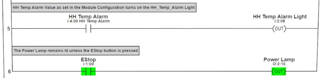
NO contact example
Greater Than or Equal To (GEQ)
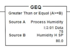
GEQ
Source B – Preset High value setpoint. If Source A becomes greater than or equal to Source B, the instruction block becomes true
In the case of the ladder rung shown below, once GEQ becomes true, (Source A becomes greater than or equal to Source B), Exhaust Fan 1 will turn on.
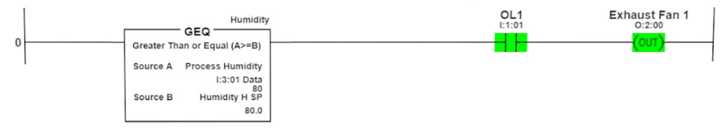
GEQ Example
Less Than or Equal to (LEQ)
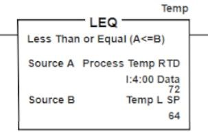
LEQ
Source B – Preset High value setpoint. If Source A becomes less than or equal to Source B, the instruction block becomes true
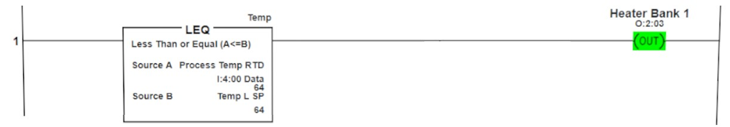
LEQ Example
Compare (CMP)
The Compare (CMP) instruction uses an expression in evaluating the existing values using only the tag names instead of the addresses.
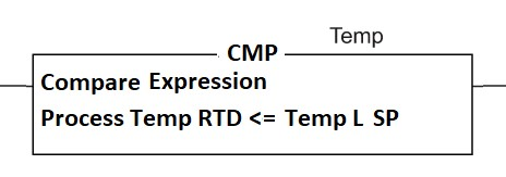
CMP
Although you cannot see the Process Temp RTD value or the Value set for Temp L SP, the information stored in both addresses is compared. In this case when the Process Temp RTD becomes less than or equal to the Temp L SP, the Heater Bank 1 will become energized.
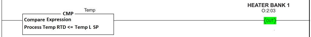
CMP Example
Outputs OUT
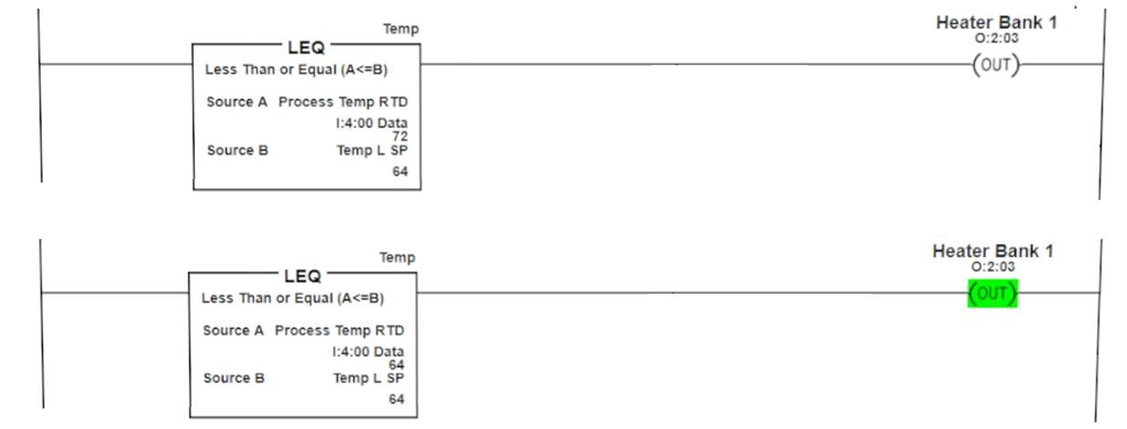
The OUT output instruction energizes when the instructions on the rung become true. In the following example, Once Process Temperature becomes equal to or less than the setpoint of 64, the output will become true. As soon as the Process Temp rises above 64, the rung becomes untrue. This can cause cycling of an output where an output might take some time to stabilize.
PLC OUT
Latch (L) and Unlatch (U)
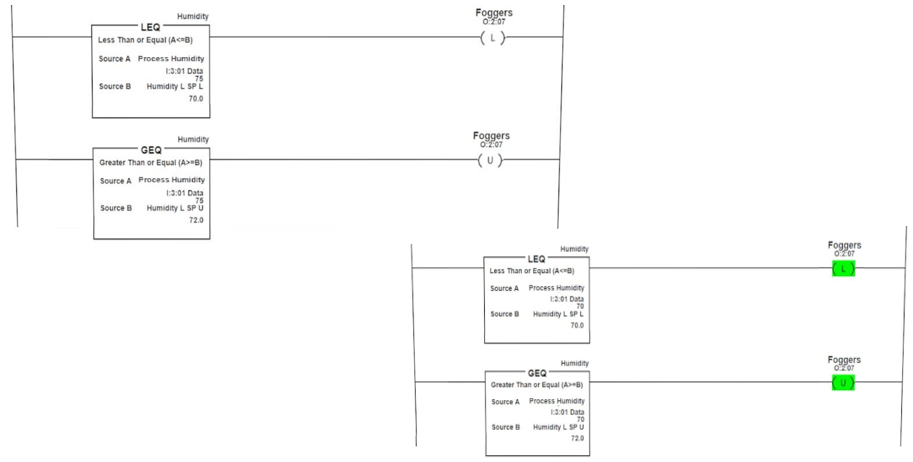
The Latch/Unlatch output instructions act as a pair. You might also see them referred to as Set/Reset or Set/Clear depending on the PLC you are using. The Latch portion of the pair will energize the output when it has met the conditions of the instruction program but then locks it into a true state until the conditions of the Unlatch are met. The Latch/Unlatch pair provide a greater flexibility and control over output release requirements. For the purpose of this simulation program, the unlatch output is being used to insert a deadband into the instruction pair. The Latch will lock the foggers on when humidity becomes less than or equal to 70%. However, it will not unlatch until the humidity level rises above 72%. This provides for a deadband of 2, allowing the process to stabilize before unlatching the foggers.
LatchUnlatch
PLC Instructions Timer On Delay (TON)
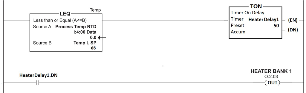
The TON instruction will start timing whenever its input becomes true. In the ladder below, the timer starts when Process Temp drops below 68°F. Anytime the temperature rises above 68, the timer will reset. If the timer completes, the .DN bit will be set, turning on Heater Bank 1.
TON Example
Accum — The real time accumulating value of the timer between 0 and 50
EN – Enable bit for the Timer
TT – This flag bit will be a 1 while the Timer is timing out and can be used in programming
DN – This bit will be a 1 when the timer has completed and can be used in programming (shown)