

GREENHOUSE SIMULATION
IntroductionTroubleshooting Industrial Sensors is a Simulation program that explores the operation of Industrial Sensors in a greenhouse setting. Greenhouse environment conditions must be closely monitored and adjusted to ensure optimal conditions for crop health and growth. The TIS Greenhouse Simulation monitors Temperature, Humidity and External light to guarantee a healthy and productive crop. The process runs continuously and needs no input from the operator. For example, if the temperature in the greenhouse falls below 64°F, the Infra-Red heaters will be turned on. If the temperature in the greenhouse rises above 82°F, the exhaust fans will be turned on. A summary of the input sensors and output devices as well as a detailing of optimum conditions can be found in the table below.
| Environmental
Elemental |
Device | Target Range | High Condition
Adjust Device |
Low condition
Adjust Device |
| Temperature | Pt 100.00385 RTD | 64oF - 82oF | Exhaust Fan | Infra-Red Heaters |
| Humidity | Capacitive Probe | 70% - 80% RH | Exhaust Fan | Foggers |
| Light | Quantum Light Sensor | 1200 μmol/s | N/A | HPS Lights |
Device Table
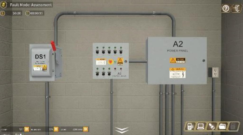
Component Layout
The Greenhouse Simulation consists of two rooms: A Greenhouse and an Electrical Room. The Component Layout image below shows the physical layout of the electrical room as well as the device location of all sensors and output devices in the greenhouse. The Component Layout Document is available for viewing in the User’s Guide.
A2 Greenhouse Layout
Electrical Room
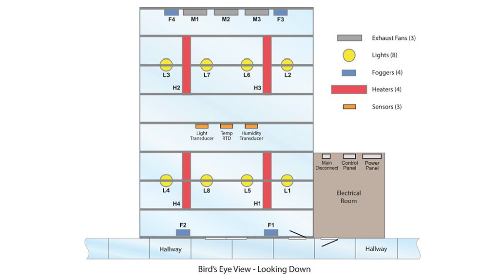
Component Layout
On-Screen Toolbars and Information
While in the Greenhouse simulation, the following onscreen information and tools are available:
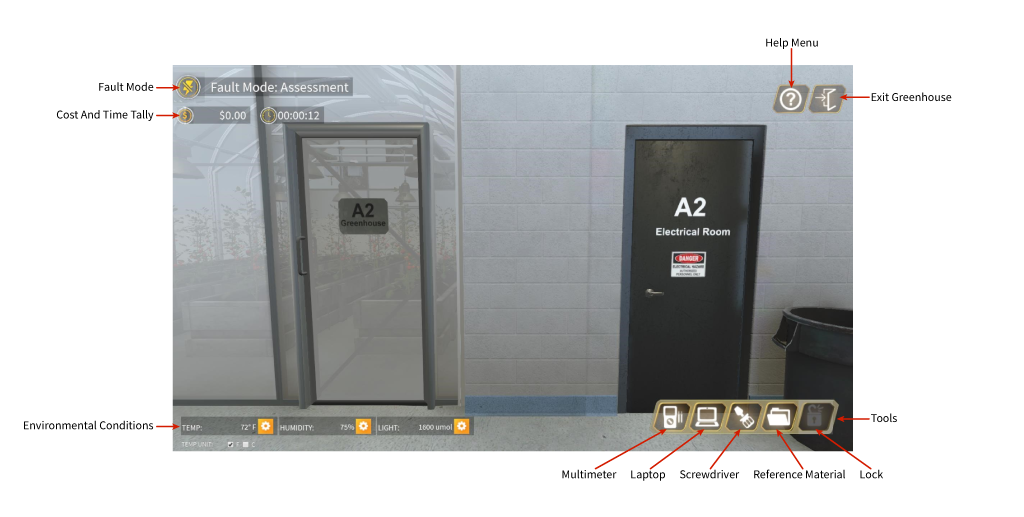
| Information/Toolbar | Function |
| Fault Mode | Informs the user of the present fault mode |
| Cost and Time Tally | For assessment purposes, tracks the dollar amout of replaced/repaired components and time spent troubleshooting |
| Environmental Conditions | Displays the actual environmental conditions in the greenhouse for Temperature, Humidity and Light. These are the vaslues received by sensor and transducers. This is user adjustable |
| Help Menu | Sends User to the Help documentation |
| Exit Greenhouse | Exits the Greenhouse Simulation |
| Tools | |
| Multimeter | Used for measuring voltage, current and resistance |
| Laptop | Used to monitor and verify process operation, contains the PLC programs and module information |
| Screwdriver | Used to disconnect and reconnect wires |
| Reference Material | Contains reference documentation such as wiring diagrams |
| Lock | Lock for Main Disconnect Lockout Tagout |
Onscreen Toolbars and Info 2